Low-dropout (LDO) voltage regulators are commonly used electronic circuit component. They take input DC voltage and produce stable regulated DC output voltage that is then used to power other circuit elements.
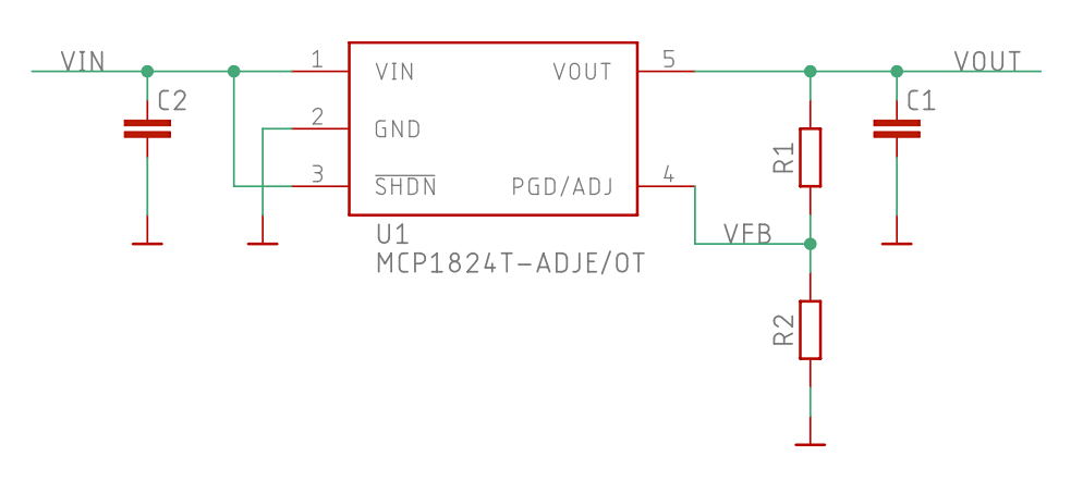
Some of the LDOs are factory-configured to output a fixed voltage, like 1.8V or 3.3V, while others are adjustable: the output voltage is set using a resistor divider (R1 and R2 in the picture below) that feeds a portion of the output voltage back into a dedicated input pin.

Knowing the desired output voltage and the LDO feedback voltage it is easy to calculate ideal resistor values. Picking standard resistor values, however, changes the resistor divider ratio and hence the LDO output voltage. Manually hunting for the best resistor divider option can be a bit tedious.
To visualize the resistor divider options when using standard resistor values—and to play a bit with amCharts—I created the following interactive chart. Best to view it on a large-screen device. Drag the sliders to set the desired LDO output voltage (for example, 3.3V) and the LDO reference voltage (for example, 0.41V).
The chart shows the best resistor divider options (most accurate output voltage) using large dark green circles. Other not as good combinations are shown with smaller circles and lighter colors. Hover over or touch the circles to see the output voltage and the resistor divider values.
This version of the chart uses the E24 (5%) resistor series. In practice you’d probably use 1% resistors for best accuracy. Scale the values appropriately (for example, multiply both by 10 or 100) to meet other requirements like limiting the current in the resistor divider.
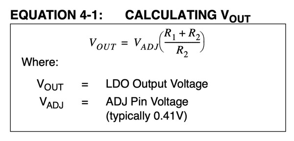
By default the chart is configured for the 0.41V feedback voltage of the MCP1824 adjustable LDO. It is listed in the data sheet as “Adjust Pin Reference Voltage” with min–max range of 0.402–0.418V and a typical value of 0.410V. The data sheet also includes the formula used to calculate the output voltage:
